-
Guest

S13 headlight wiring
Hiya guys a long time since I last posted due to the car being of the road for almost two years but many good things have happened including a full rewire (well almost) the car has gone very track orientated and pretty much anything wiring related that is not needed has been removed (this has been done by myself with an overlooking eye of my nextdoor neighbour who has taught me wiring) but I'm still left with the headlight wiring it seems the only diagram I cannot seem to understand or am getting confused with. Basically I'd like to simplyfy it as much as possible so the lighting switch does the normal side main and full and the headlight retract switch just makes the headlight go up and down. I'm not bothered about if I pull the stalk to flash it automatically lifts the headlights etc I just want super basic functions. Really appreciate if somebody could modify the diagram on EL 37 to aid me
Thanks for any help Mike
-
Guest
this is all from memory...
from memory the square box on the diagram with the dots inside tell you what each phase of the stalk does.
i found the US version of the headlamp circuit made more sense.
the stalk just switches the relay grounds, if you try to run the headlamps through the stalk you will cook it, it will keep your right hand warm though.
the headlamps run through the timer relay so that they don't illuminate when the motors are still winding up or down.
the difficulty with the motors is that you need to switch the input signals to send them either up or down. so its not just a case of using a relay triggered by the headlamps being turned on or off. this is what the motor control box does. I did thoink that you could use the headlamps being turned on to activate a relay to raise the motors but then you would need another relay that somehow is activated by the headlamps being turned off to send them back down again.
my unofficial advice is to stick 12v up the various wires on one of the motors and see what you may find........ a double pole double throw switch may become a feature.
be sure to turn your dipped beam off when running main beam or you will melt the headlamp sub looms. its a nice idea though to get decent brightness.
-
Guest
I had a feeling it might not be that simple. I could understand some bits like you mentioned the box showing the functions of the stalk. I dont mind using relays as currently my custom fuse panel has the 4 headlamp retract relays on it and are currently wired in the factory way I was just tlooking for a way to reduce the relays and maybe remove the dim dip and the timer etc to reduce the amount of wires and complexity
-
Guest
the motors them selves have a built in circuit that will make them stop at the required point. you just need to stick 12V+ up the relevant wires. I just wired the motors through a separate switch (DP-DT). so I have to put them up then switch the lights on. although I quite often just leave them down with the lights on for my own amusement.. when the motors reach their stop position they stop drawing current.
it was only a month or so ago that I got the brain wave that I could have wired the motor relay to the headlamps so that they would come up when the lights were switched on. by just feeding into the control side of the 'up' relay. although im not sure how you would wire the 'down' relay to work when the lamps are switched off.
I also put my main beam on a foot operated switch above the footrest like on an old landrover as it leaves your hands free.
-
Guest
Hi thanks for the reply that's good news then it does mean that I can ditch all the units/modules and it will still work just manually which I have no problem with doing like I said the simpler the better I even toyed with the idea of just have the lights static and only wiring the stalk if it became to much of a problem. If you could draw or scribble a basic diagram just started to get me started that would be great
Thanks again
-
Guest
I really don't know how to post images on here TBH.
its not a difficult circuit. just see what amps the motors draw when you power them up.
-
Guest
Dim dip unit can be junked and these wires connected. Clearly you can strip the loom back.
https://www.sxoc.com/vbb/showthread....light=headlamp
sorry I can't help much more with the retract timer but you can at least remove the wire that goes to the side-lamps switch (pin that i snip).
-
Guest
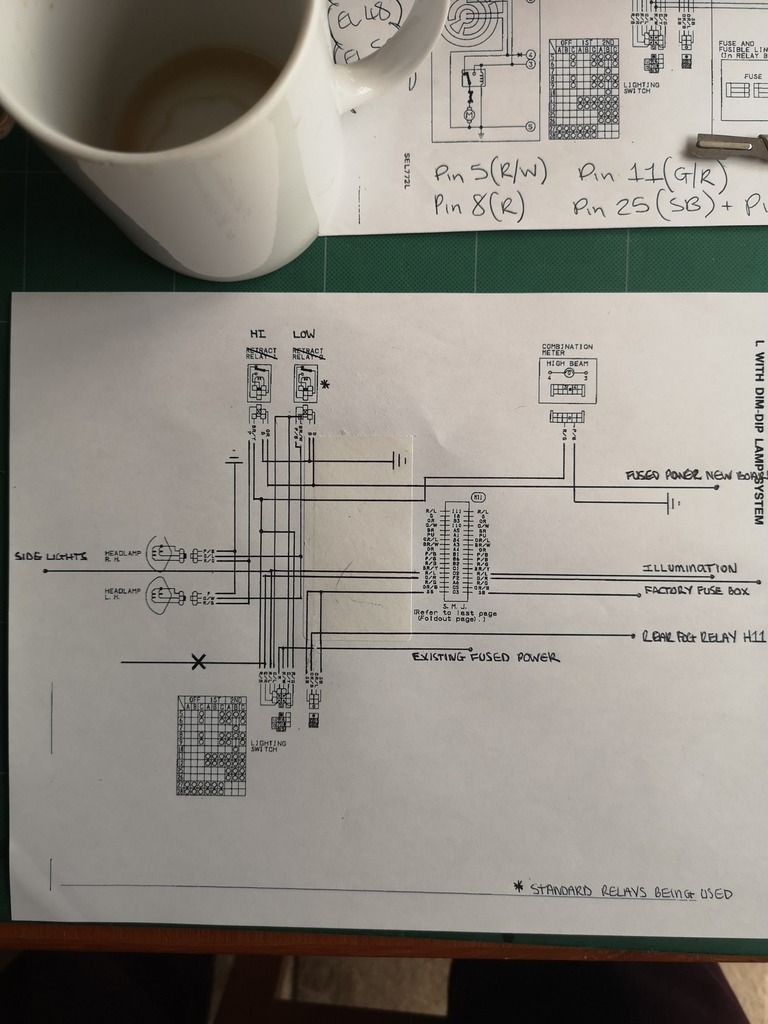
Hi guys I drew up a diagram of what I plan to do to make the stalk work like normal with the everything else removed. If somebody could check it over see if I have missed anything before I get snipping haha
Thanks again for all the help and suggestions
-
Guest
your image don't show for me mate.
-
Guest
That's very strange I just got a friend to have a look at the post and he could see it I'm not sure how else I can upload it
I've tried a few different like here hopefully one will work

Last edited by fikemoo; 22-01-2019 at 10:14.
-
Guest
it was my out of date browser.
just try it see what happens. I don't have an OEM diagram to compare to but it looks like your staying fairly stock on the wiring.
what did you decide to do regarding the pop up motors?
-
Guest
Fair enough. And yeah I'm using as much of the factory wiring that's already in place just ripping out the rest I dont need and adding new where I need to. For the motors I'm going to try and do the same and work out what pin is doing what and build my own separate basic circuit that works from the retract switch as a simple up and down.
-
Guest
Fair play i just removed all of the OEM wiring and started again.
-
Guest
I'm interested to see your results as mine are manual at the moment  and im no where ear as electronically savvy as you guys seemI do have some origional wiring diagrams i could share if they'd be an use though ?
-
Guest
the OEM diagrams are proper head benders.
 Posting Permissions
- You may not post new threads
- You may not post replies
- You may not post attachments
- You may not edit your posts
-
Forum Rules


 Reply With Quote