

That diffuser looks sweet!
Have you considered the effect it might have on the diff getting adequate airflow for cooling? From the pictures it does look like the diff will still be getting some air.

That diffuser looks sweet!
Have you considered the effect it might have on the diff getting adequate airflow for cooling? From the pictures it does look like the diff will still be getting some air.
I don't see the differential suffering from a reduction in airflow as the diffuser is behind the differential, if the diff does get hot and start to slip then its something I could checkOriginally Posted by fridx

Top work mate, great project.
1998 Nissan 200sx s14a , 2000 std 5 speed with nismo supercoppermix clutch bn6 Sapphire Blue
Thanks buddy, I will get you that draft post ASAP.
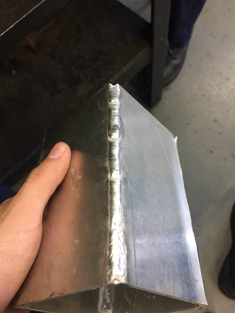
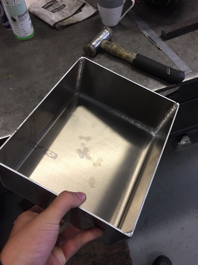
Did some more welding practice and made a start on the tank sump today. Started by joining two 1.6mm sheets of 5083 together, this was ok. I wouldnt want to have to weld much thinner though, this short amount caused warpage even with the copper block underneath!
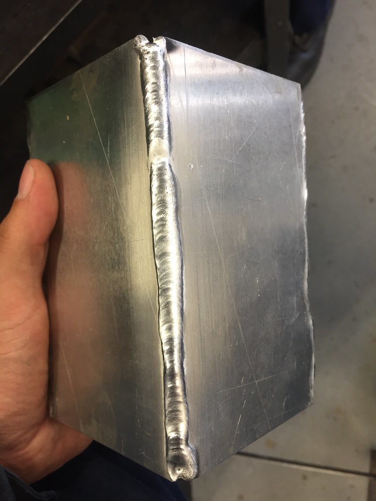
then moved onto outside edges. I think these were the easiest to do. and on the third attempt (bottom picture) I was happy with the bead shape and penetration.
2nd go
3rd go
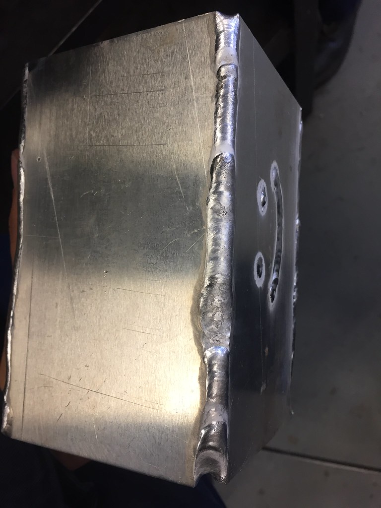
However my inside edge beads were terribleand all the pictures magically disappeared....
so graham said he would weld up the sump so it wouldn't leak.
top jobgoing to order a few more fittings from Torques tonight ready for the sump plumbing and I need to find the Walbro 255 that's in my garage somewhere.
So today was good.
the 5083 Ali turned up and waaaaaaay too much was ordered.
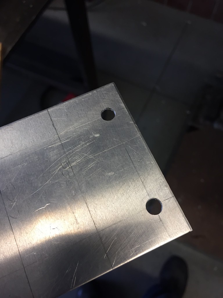
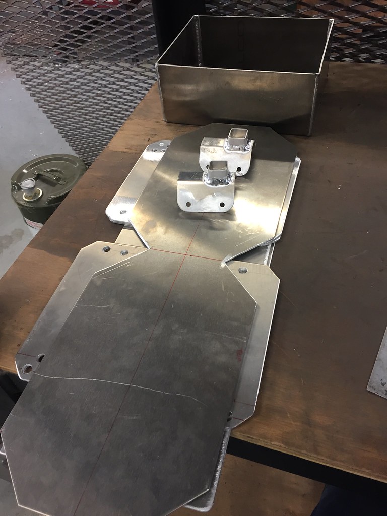
the first thing i wanted to get done was to make a mount for the in tank lift pump, i'm planning on using a Walbro 255 to fill the surge tank. This is another step by step job. I took some squares of the 3mm sheet and marked them up.
then drilled them out so that a cable tie would fit through. I figured its easier to drill them now than after they were bent up.
then de-spikefied the edges, the last thing I want is to reach into the fuel tank and carve my hand open...
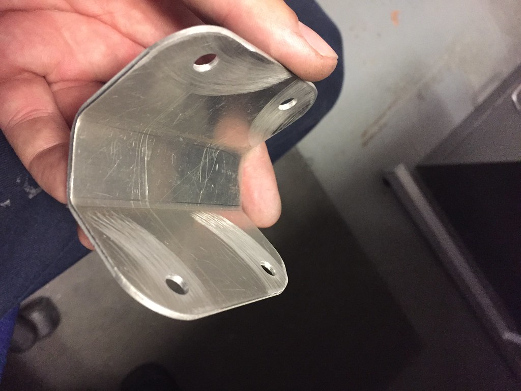
Then I bent them up, its about a 30 degree angle each side with a 25mm gap inbetween the two bends.
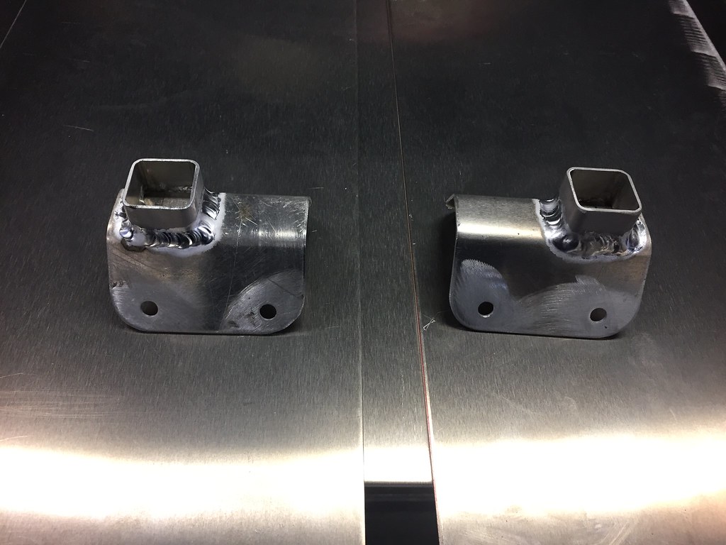
then cut some 1" Ali box section to make a mount, the original plan was to put this mount n the middle of the back of the plate, but when I had concerns about getting the TIG torch in to weld it into position.
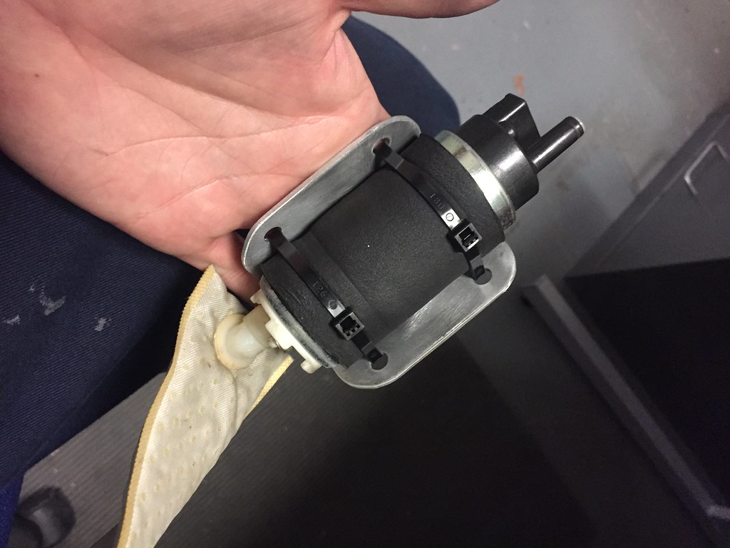
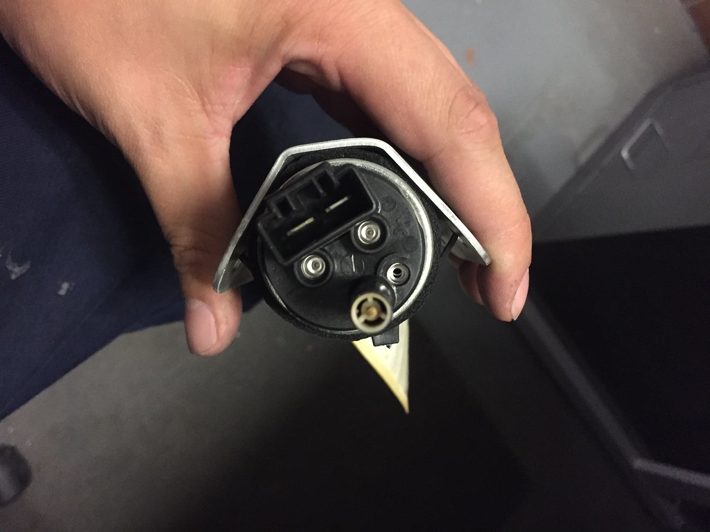
test fitted the pump it sits in really nicely and doesn't move even with violent motion..... I must admit i did drop it while i was shaking it so i will need to test it tomorrow to make sure it still spins up ok.I will also look for a new filter bag for the pump as that one has been sat in my garage for three years. if anyone has a link then please let me know!
Then graham welded up the pump mounts, the Ali box section was really crap and was super hard to get a pool formed on. Best let the pro do it. as you can see the mounts are at the "top" and yes there are two pump mounts going in. It makes sense to future proof the build.
I also managed to fold up the main part of the tank, the end plates are also cut but not pictured. I still have to cut the tank baffles too.
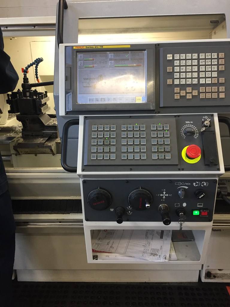
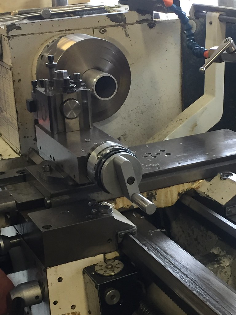
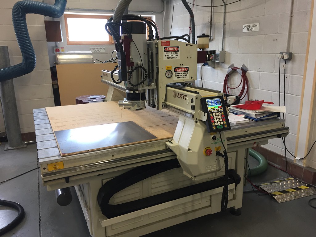
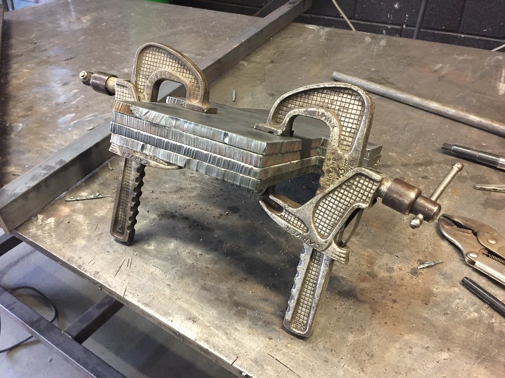
Then I went to get on the lathe in machine shop. I used lathes at school.... these are more modern
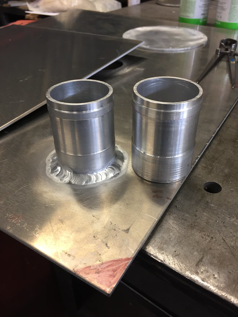
I will speak to wynn tomorrow. I have a piece of 200mm billet bar that I will turn down into a ring, then I will drill and tap maybe a dozen holes into it and when its welded to the tank it will be my access panel.
you can get deburring tools for cutting the sharp bits left from drilling holes. and rounding the sharp edge left from cutting sheet in a guillotine
http://www.advancedengineering.co.uk...eburring-tool/
they have a few different 'blades' for different purposes. although I tend to just use the 'blind hole' one for most things.
they cost about a fiver.
There is a few deburring tools in the workshop but the air grinder was in my hand
Plus everything has to be crazy clean and degreaser for TIG welding
embedding grit into the alloy from grinding it with an abrasive discs don't help keep it clean.
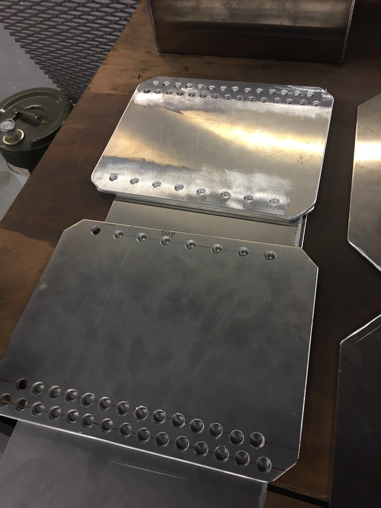
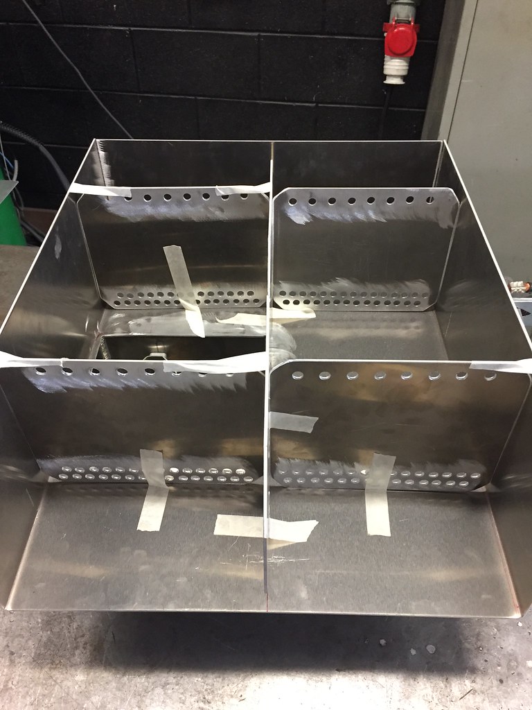
finally got all the pieces cut and prepped for welding today!took so long. had to drill soooo many holes in the baffle plates it was ridiculous.
drilled nearly 160 holes. definitely didn't use a de-burring tool for those bad boys
these are the lateral baffle plates. they are slightly offset inside the tank about the logitudinal baffle so two are 255 wide and two are 245 wide.
then this is the longitudinal baffle plate. mega simple. 50mm notches cut to allow fuel/air movement.
If you want to nerd out on the maths 6 50mm triangles have an area of around 225cm^2, cut from a total area of 1200cm^2 gives an 81.25% reduction in the area the fuel can slosh through.....
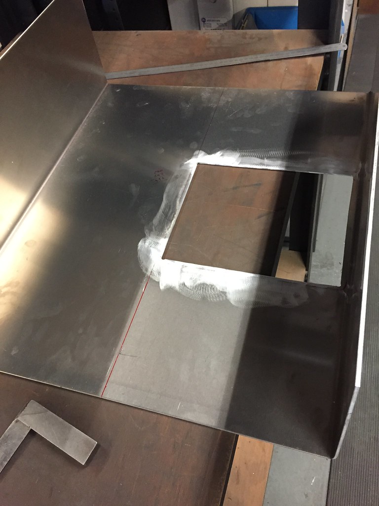
The hole for the sump was also cut.
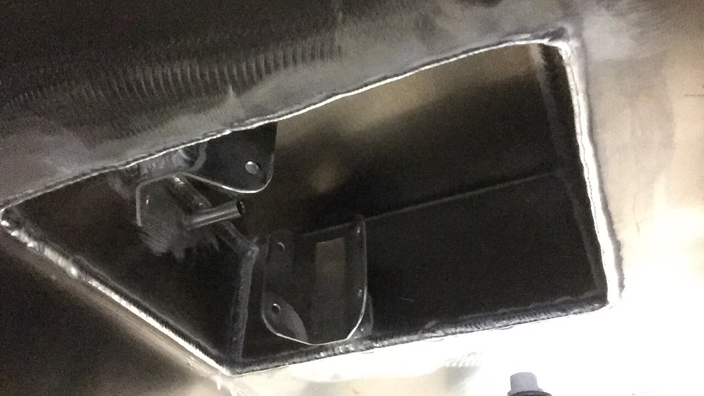
sump was test fitted. (apologies for the slight blur)
Then all the baffles were test fitted. awwwww yeah.
waiting on the last two fittings from Torques UK that will be here tomorrow and then will probably get round to welding it up on monday morning!
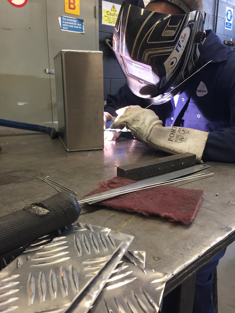
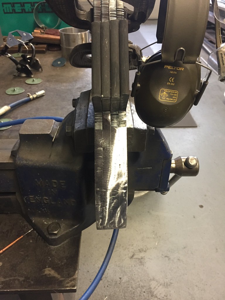
one other thing we did do was to weld some test pieces up, annoyingly I didn't get pictures but the results are quite important. we welded 5 pairs of 3mm 5083 together at right angles using various filler rods on the outside edge, then smacked them with a hammer to see what might happen in an impact.
they all shattered except the N3 filler rod
that bent instead of snapping. so we will use the N3 rods to put the tank together. will maybe run the test again to get a video or some pictures for you guys.
This is true, but starting with a 120 disc then sanding it flat up to a 400 one smooths it out nicely for welding. I've not had any problems doing it this way and the surge pot held pressure beautifully.
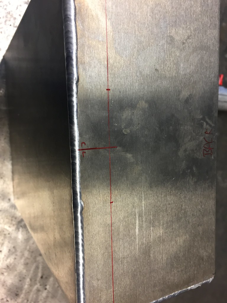
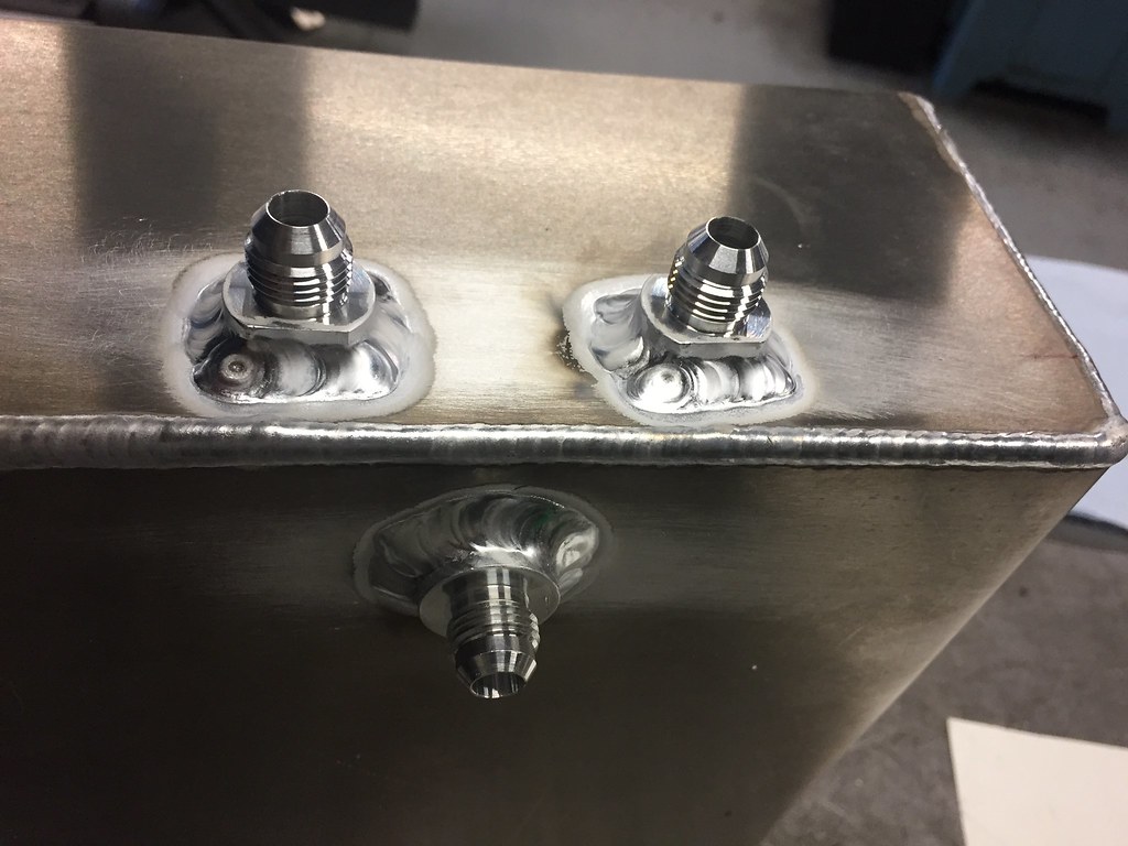
got some more done today, the last few fittings arrived on friday so holes for them were marked and drilled in the sump.
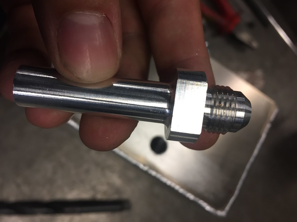
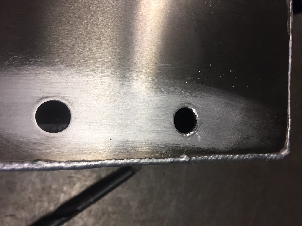
annoyingly there is a slight radius between the face and the stem. I got round this by counter sinking the hole slightly, in the second picture you can see this on one of the holes.
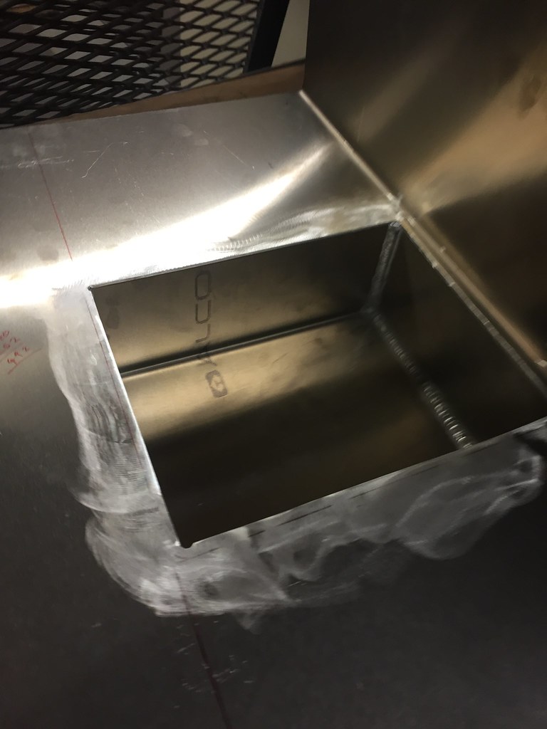
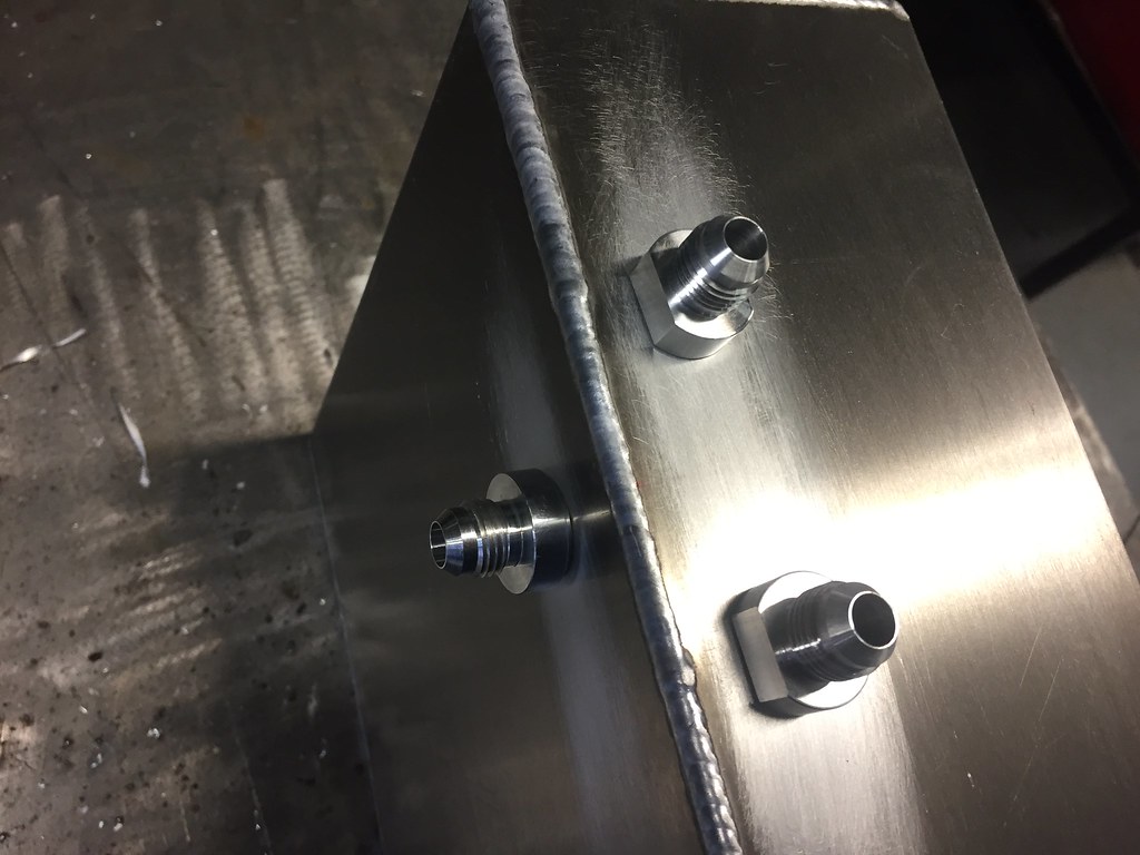
The everything was checked for fit and welded.
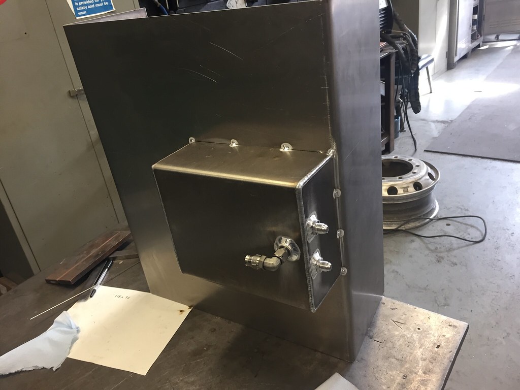
sump tacked in place.
then the pump mounts were welded in place. in this picture the sump is fully welded to the tank.
also a lot of the welding on the baffles is done, I didn't take pictures though because I was getting abit annoyed at heat distortion. even using 3mm Ali with copper heat sinks it still warped. tomorrow I will try to normalise it and get it back into an acceptable shape. If i cant i will have to start over
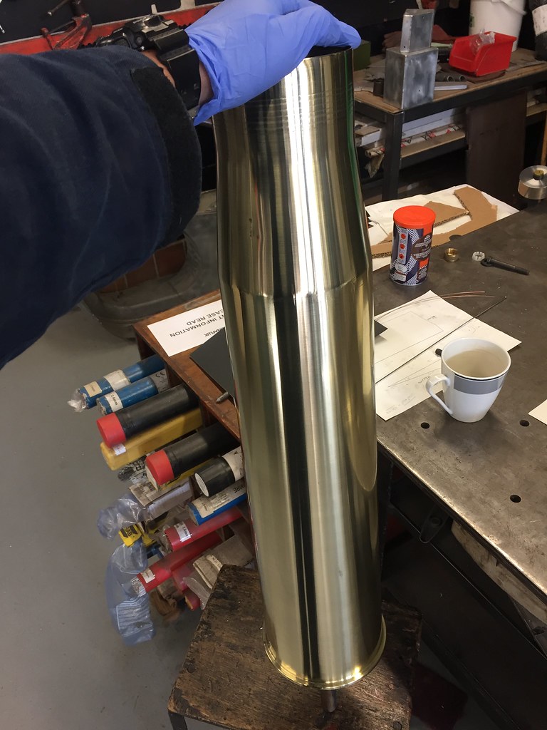
I also got distracted by this coming in too. 4.5" naval gun shell that the guy wanted polishing, so I removed the spent fuse cut it down and flipped it in the shell.
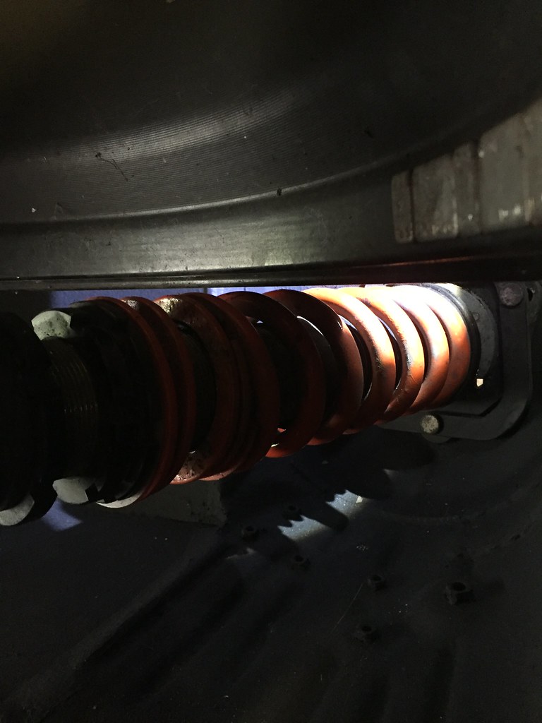
stuck it in the lathe and set the speed to ~260 RPM then used 400 grit paper to clean it up.
then used brasso (still on the lathe) and a rag to polish it. I believe its off to the paint shop here next for a coat of lacquer to lock in the shinys.
will get back to it tomorrow, finish welding up the baffles and remove the heat warp with graham, cut the tank lid on the guillotine and mark it up for the sender unit, tank lid and other pipes. will have to get back on the CAD lathe to machine out my chunk of billet to form the tank lid ring.
Nice work.
And me want that gun shell !
Sent from my iPhone using Tapatalk
Good progress.
How would you go about removing heat warp? Is it possible to get the ali back completely flat again?
to be honest some of it took itself out when graham finished welding up the baffles, the rest we were able to smooth out with a hammer, Aluminium is a very forgiving material.
didn't achieve a lot today, I did manage to turn a slight lip into the filler neck for the tank lid but now I am waiting on things to happen in other workshops and to come back to me. bit of a danger photo using the automated feed and leaning away while its turning towards the chuck
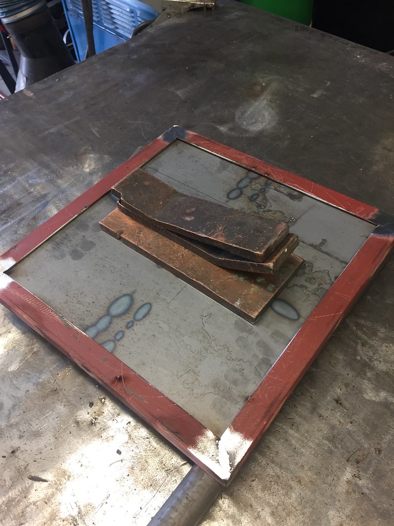
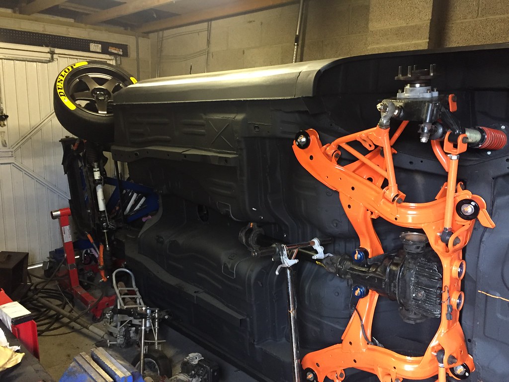
as work has slowed on the tank i have moved to a few side projects for the car. namely making some set up hubs and stands. (for those who dont know HUBStands) there is no way im paying that much for them though. I have used the while working in the pits at BTCC events and they are great, you can adjust the cars set up with the weight on the wheels, much easier than jacking, adjusting, lowering moving, checking......
for the plates I dug out some 5mm steel plate, put some 3mm angle round the edge and braced up the bottom of it. I have ordered some adjustable tilt feet and will drill and tap some holes for them later. I officially love the guillotine at work. absolute beast.
The copper plates are there to draw heat out and help keep the plate flat. all the angle iron does is stop the car rolling off the edge of the plate.
as for the hub brackets I have a piece of 12mm plate (dreading cutting that...) and have measured out a template that i will transfer onto it and then use the plasma cutter. the holes for the studs and hub center will be CNC milled out and a bottom added maybe from 8mm steel for the conveyor ball bearings.
the other thing I have started gathering bits for is the "strings" to go with this. again these things are really expensive and really simple. once I get mine made I could bring them to events or meets and people could use them to check alignment and make informed changes. maybe.
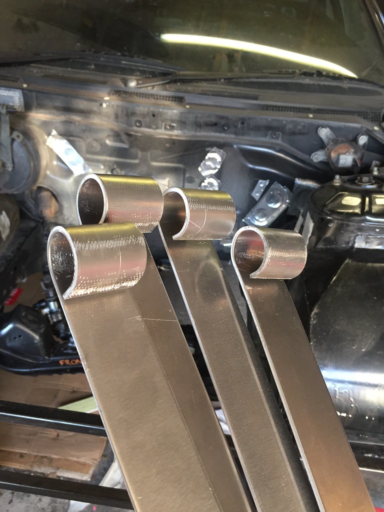
I cut aload of 1000 x 40 strips of 3mm Ali today and got some 20mm tube and 25mm box ready to start chopping into.
also making some chickens for tyres but that's a different post.
I didn't bother going into work today or yesterday
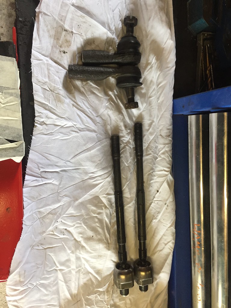
decided to sort out an issue i have been putting off. steering arms. specifically mine being 20mm to long each side. I started planning to make some utterly bomb proof bad ass full custom setup rubbish. Then realised i was being thick and could solve the problem with a hacksaw and 5 minutes. so.
take one TRE and one track rod. slice 20mm off the end of each, clean up the threads. done.
did the other side and reassembled them. the wheels are now within maybe a degree of each other and true. better than each wheel toed in by 15 degrees
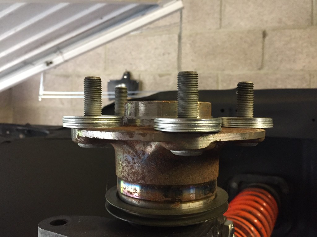
then chucked a wheel on to see what was what. got scared by how little clearance there was.
then I remembered that i hadnt put a brake disc one because I have no brakes for this vehicleso a quick dig through my spares bin found me some 12x38 washers in surplus. guessed at 5 per stud, probably a bit thinner than a brake disc (comments welcome please) but it opened out the gap a bit.
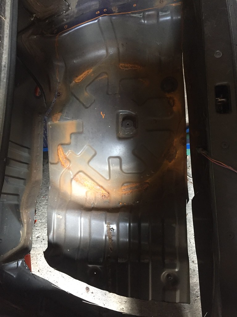
put the wheel back on and its ok, had to bend abit of a flap on the chassis rail out the way and fiddle with the bump stops for the steering but I can get ok angle now, some refinement of the setup should see more locku. not that I will intentionally drift this thing.
after that pretty much left it for the day. if i can find brkaes (unlikely) or more washers (probably) i might put it on its wheels and let it see the sun.
bit of a bigger update this time, lots of odd little things.
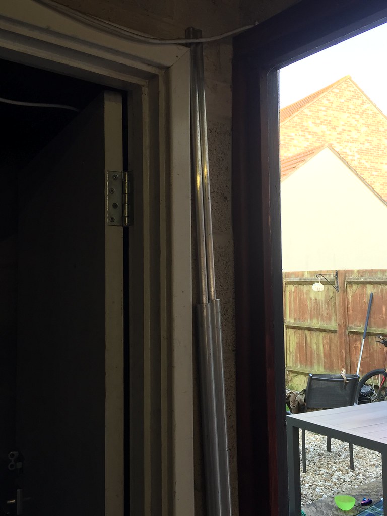
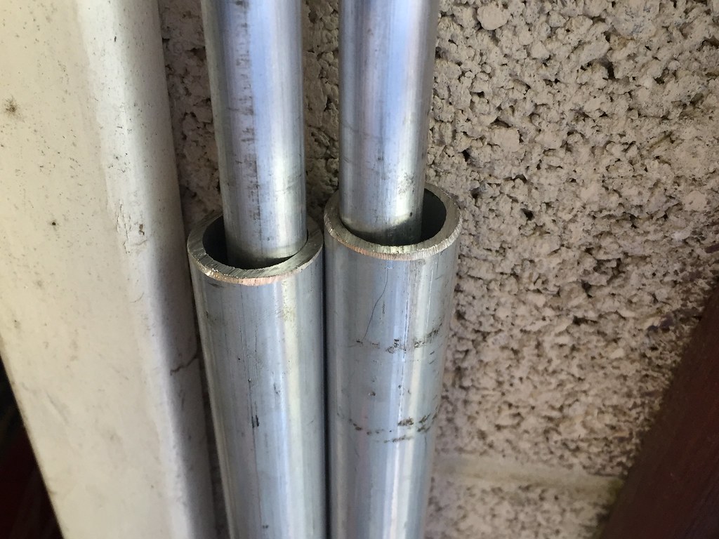
made and cut the alignment jig arms (poles?) to length, the tube is 1600mm and the bar is 2100mm long enough for even a wide car with poke.
it may look loose but it will be fine once the string is on and under tension if it does still move (which it wont) I will make some collars to be inserted.
Also got the "ski's" made up, the tube goes through these and then these are bent to fit the car so they are at the right level. such a simple concept.
Also need to say thanks to Matt, he found time to put my fuel tank lid on the CNC router. cool piece of kit. whipped up a CAD file in about 5 minutes and cut the holes exactly where i needed them, no mention of the circle of shame matt!
Then welded the filler neck on, I left it like this so I can decide later where I want the fuel filler point to actually be.
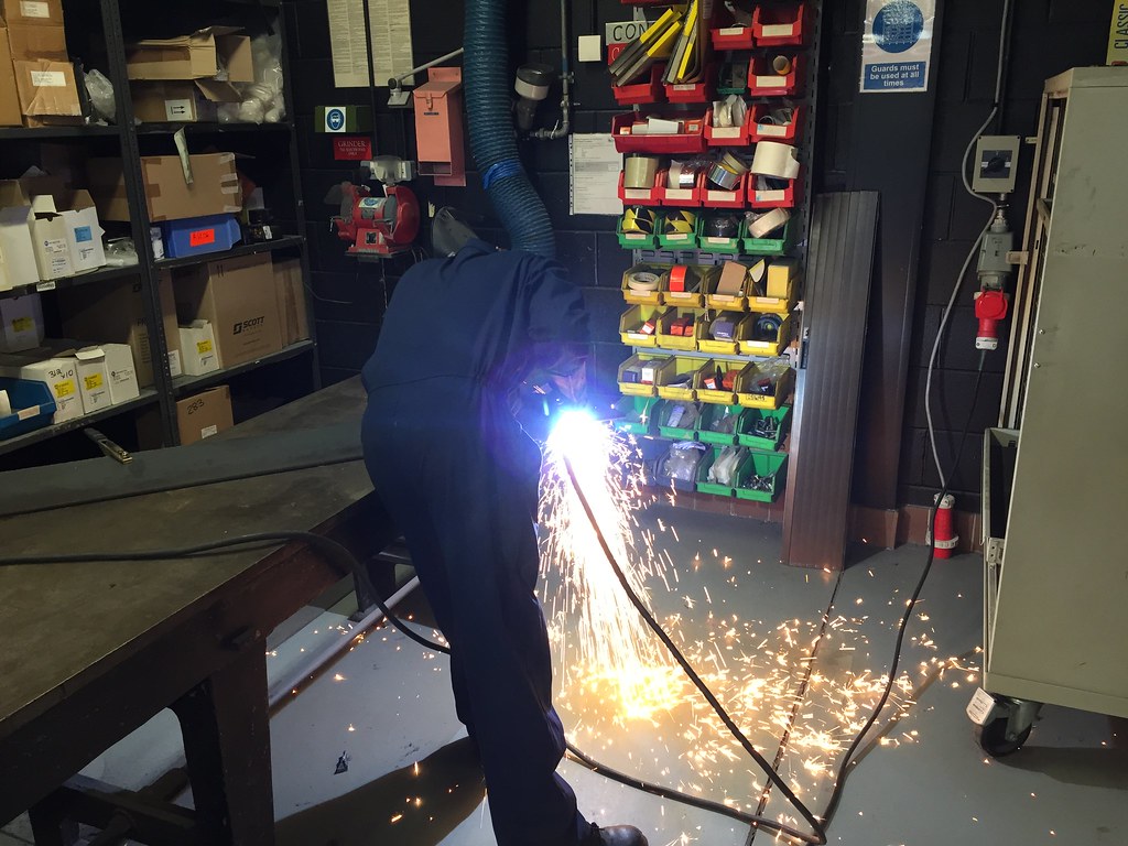
then things got fun! today i decided to make the set up stands that actually bolt to the car hubs. pulled the piece of 12mm steel sheet out and did some marking out, then graham let me loose with the plasma cutter. what a machine!!!!!went through 12mm plate like it wasnt even there. love it. felt like a jedi or something
much chopping and drilling was done.
then some clamping. Thats damn near 2 inches of steel there!!!
now I am at the stage of grinding the edges so they look smart and are of a similar size. powder coating will hide the rest. If youve never had the pleasure of grinding a 2" plate..... dont.
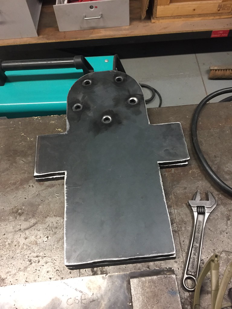
All that effort just to make a few gingerbread men
Sent from my SM-G920F using Tapatalk
Pretty much
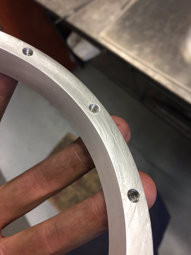
so its been a rough few days. The ring for the tank lid was lathed to perfection by Wynn ( he is welsh and his name is actually spelled something like ioananinayaanioana but i'm damned if I can remember how it goes)
each hole wwas tapped with an M5 x 0.8 lead and finish tap. took ages. looked sweet.
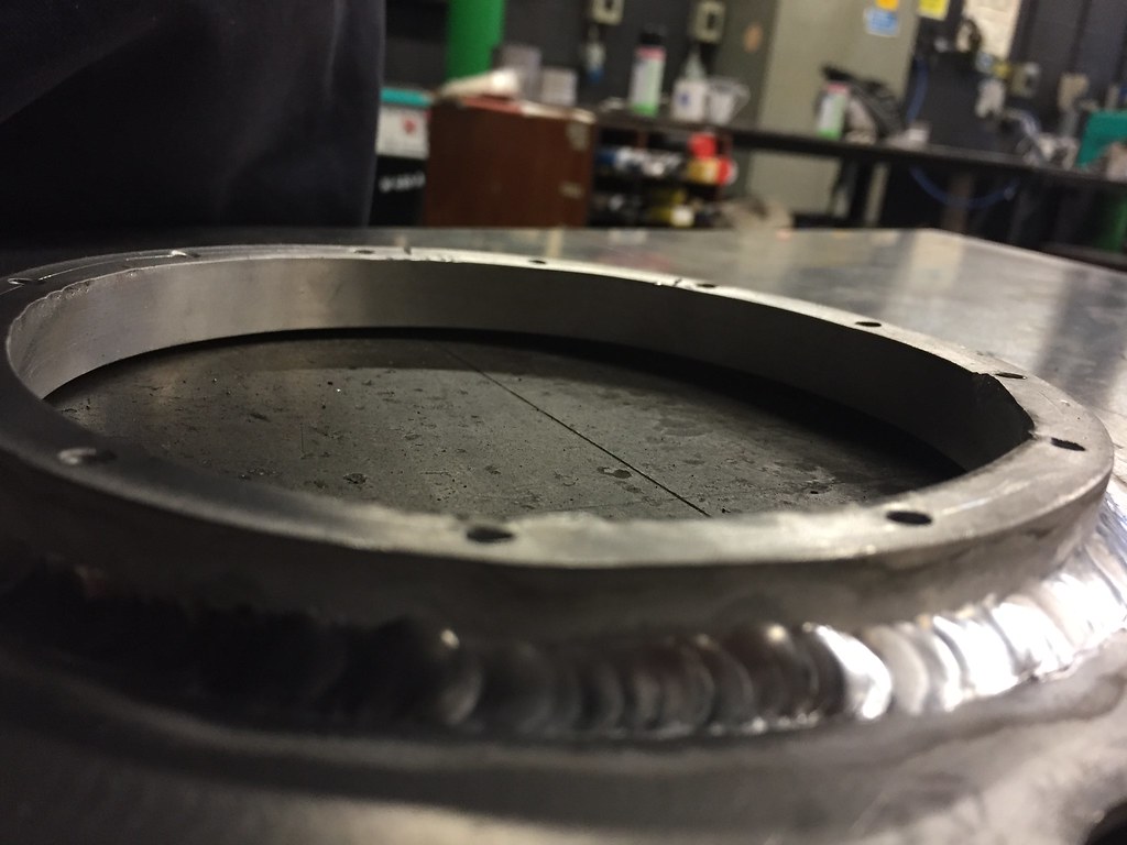
then... tragedy. when it was being TIG'd in it warped, we were expecting some warp but not in the plane it twisted in, it tried to roll through itself and kinked. effectively this made the tank lid a write off, we couldn't untwist, straighten and flatten it.
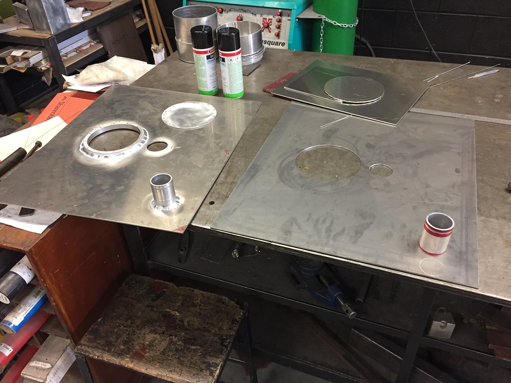
But this kind of crap happens. so a fresh piece of 5083 was thrown in the CNC router and a button was pressed. and I drew on a piece of tube. which led to...
bit more lathe time got me a second filler neck turned out.
and this was welded in. and cooled with copper plates.
In other news the plates had the center holes milled out. courtesy of Nobby.
also when I got back I eagerly got them out the car, went straight to the garage almost ran to the back hub in anticipation and the stupid things don't fit. b*llocks. on of the holes is about 1mm out
So in summary in the last 5 weeks ive started loads of little projects for my car and finished none of them
im surprised you didn't just get your stands laser cut. what size holes did you cut for the wheel bolts?
I made my 'setup' poles (the ones that go at the front and rear that the string connects too) so that the fitted onto the car.
Last edited by green_rs13; 04-09-2017 at 18:24.
 Posting Permissions

 Reply With Quote