Page 1 of 2 12 LastLast
Results 1 to 20 of 36

Thread: Pictures of my shed of an S13... can you work out what it is yet?

  1. #1
    Guest Adam-Murse's Avatar
    Join Date
    Jun 2012
    Location
    Teesside
    Posts
    284
    Rides
    0

    Pictures of my shed of an S13... can you work out what it is yet?

    I was going to start a project thread on this, but i don't have access to the page or something. So I thought I'd pop these pictures up here of my total waste of metal that was a nice S13 before some bodge merchants got their hands on it...


    Anyone have any idea where these pipes are ment to go to? they are vac pipes I think (I'm new to turbos so sorry for the noobness)


    I love this... relay box thats not held down anywhere, anyone know why?


    Random wire spliced into what i think is a lambda sensor on the turbo elbow (is it the turbo elbow?) anyone have any idea what it might do?


    Cam cover breather... I'm guessing a pipe should be attached to it? any ideas people? lol

    also note some random wireing... more pics to come of that mess soon


    more cam breathers that have no pipes :s


    and this one I like... does anyone know what it is? why it's just got a ton of instant gasket on it (instant gasket seems to have been on offer for the cars previous owner, more pics coming) and why it's held together with electrical tape!!??


    more pictures coming of the mess the cars in, but thats some fun to begin with lol

  2. #2
    Guest chapman-s13's Avatar
    Join Date
    Dec 2007
    Location
    wimborne
    Posts
    1,411
    Rides
    0
    the breathers should go across the top over to your instant gasket electrical taped idle control valve there should be another breather there?

    the extra wire on the lamber plug could have been an attempt at a wideband gauge failure

  3. #3
    Guest Adam-Murse's Avatar
    Join Date
    Jun 2012
    Location
    Teesside
    Posts
    284
    Rides
    0
    Quote Originally Posted by chapman-S13 View Post
    the breathers should go across the top over to your instant gasket electrical taped idle control valve there should be another breather there?

    the extra wire on the lamber plug could have been an attempt at a wideband gauge failure
    So the thing thats taped up is the idle control valve?

    And the breathers off the Turbo should go to the Idle control valve? I couldn't see anywhere on the ICV that the breathers would go to? I'll go have another look

    every car I've worked on the ICV is on the throttle body, so good job I asked

  4. #4
    Guest McLarenboy's Avatar
    Join Date
    Aug 2007
    Location
    Belgium
    Posts
    323
    Rides
    0
    The last pic is the AAC valve, plays a vital role for the idle of the engine? This needs to be airtight or the car will have trouble running smooth. Looks dodgy to me, you should consider scrapping it and getting a proper one.

  5. #5
    Guest Adam-Murse's Avatar
    Join Date
    Jun 2012
    Location
    Teesside
    Posts
    284
    Rides
    0
    Quote Originally Posted by McLarenboy View Post
    The last pic is the AAC valve, plays a vital role for the idle of the engine? This needs to be airtight or the car will have trouble running smooth. Looks dodgy to me, you should consider scrapping it and getting a proper one.
    funnily enough the car wont idle! lol

    scrap what? the AAC?

  6. #6
    Guest
    Join Date
    May 2010
    Location
    Gloucester
    Posts
    383
    Rides
    0
    Ill go for the easy one... vac pipes on the turbo, they should in theory be linked together. its how pressure (boost) is controlled in the turbo. the brass thing on the turbo is the wastegate actuator. which opens the wastegate to let fumes out into the exhaust, instead of pushing it round the turbo creating more boost.

    looks like there was a boost controller in there hence the pipes not being connected

  7. #7
    Guest Adam-Murse's Avatar
    Join Date
    Jun 2012
    Location
    Teesside
    Posts
    284
    Rides
    0
    more pics


    Now some random wires


    If anyone can confirm what any of that is then well done! lol

  8. #8
    Dorset & Hants Rep pointz's Avatar
    Join Date
    Sep 2009
    Location
    southampton
    Posts
    7,901
    Rides
    0
    the 3 blocks in the last pic would of went to ABS unit, 2nd to last looks like lambda sensor wiring but i dont have this. i'd say its been spliced for wideband as said previously or could of been for a turbo timer, 5th from bottom looks as though the wire has had a new connector crimped on (or bodged together) for washer bottle, 7th from bottom possibly for an alarm you can see the bracket that looks like it held the siren, 9th from bottom relay for electric fan or some sort of lights??,12th from bottom looks like the wire that goes to coolant temp sensor just behind thermostat housing!

    hope that helps a little and good luck sorting that mess out!

  9. #9
    Dorset & Hants Rep pointz's Avatar
    Join Date
    Sep 2009
    Location
    southampton
    Posts
    7,901
    Rides
    0
    suppose this raises the question whats the rest of the car like?

  10. #10
    Guest
    Join Date
    Feb 2004
    Location
    Burton on Trent
    Posts
    11,209
    Rides
    0
    There should be 3 small vac hoses connected to hot start solenoid under the ignition amp on nearside wing. 1 should come from the small stub on inlet trunk near AFM. 2nd goes to stub on rear of plenum. 3rd goes to the Fuel Pressure Regulator. Even thoughI have a dead one right here I have no idea which port on the hot start valve is which. Most people put a bolt in the inlet trunk and connect the FPR direct to the rear of the plenum. Throw the hot start solenoid away - all it does is the flood the engine.

    Sorry I have no recollection as to how the relay box is secured other than it's parallel to the front bulkhead. Some people strip the contents and shove them back though the hole into the wing. They then leave the arch liner off and wonder why all the electrics have got soaked and shorted out.

    That lambda wire looks burnt bare. Middle wire is sensor, it's a voltage source like a battery, produces 1V when hot and oxygen present. Outer 2 wires are heater, one is bat volts other gets earthed by transistor in ECU.

    Inlet cam cover breather goes rearwards to a T. The leg of the T goes to the PCV valve on rear cover of plenum. Other end of T goes to the exhaust cam box breather that points at inlet cam box. Exhaust cam box breather pointing forward goes to inlet trunk just after AFM. If you have none of that. Blank the PCV port off. Fit hose from inlet cam box to exhaust, then put the other leg of exhaust breather into a catch can.

    The idle air valve needs removing. the gunge scraping off and some thick paper gaskets making. It's held to the manifold by 3 bolts 2 of which at least are present. Is the tape holding the base Idle bolt in place on the rear of the assembly? The idle air feed hose (with lose hose clamp) goes to a metal tube that threads between 2 ports on the plenum. Hose goes from that tube to a T hanging near the throttle. Leg of T goes up to the air regulator (cold start fast idle) under throttle which then connects to port on front inner side of plenum. Other side of T goes to the stub on the plastic cross duct from the intercooler or a stub on the IC outlet duct.

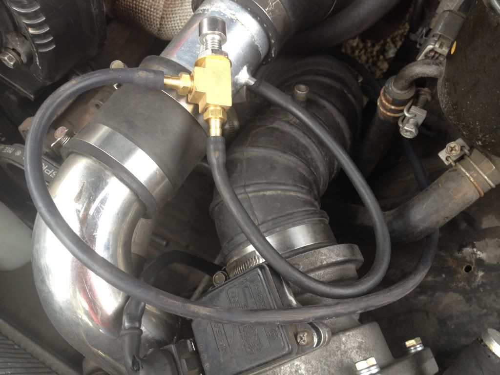
    There are no breathers on turbo. You appear to have a T28 (or better) with bolt on inlet. The actuator hose should go to a port on boost side of turbo. Some people connect them to the stub pipe just behind the throttle on plenum - also use this for boost gauge and you better have one. Or fit a nipple on the turbo comp housing. Or fit a screw in nipple on a silicone boost pipe. If you have chip then it needs a boost controller in the line.

    Now who on earth has been painting bits purple and left it in that state?

  11. #11
    Guest Adam-Murse's Avatar
    Join Date
    Jun 2012
    Location
    Teesside
    Posts
    284
    Rides
    0
    Quote Originally Posted by pointz View Post
    the 3 blocks in the last pic would of went to ABS unit, 2nd to last looks like lambda sensor wiring but i dont have this. i'd say its been spliced for wideband as said previously or could of been for a turbo timer, 5th from bottom looks as though the wire has had a new connector crimped on (or bodged together) for washer bottle, 7th from bottom possibly for an alarm you can see the bracket that looks like it held the siren, 9th from bottom relay for electric fan or some sort of lights??,12th from bottom looks like the wire that goes to coolant temp sensor just behind thermostat housing!

    hope that helps a little and good luck sorting that mess out!
    that helps allot thanks!... and allot of what you've said there makes sence

    Quote Originally Posted by pointz View Post
    suppose this raises the question whats the rest of the car like?
    the car it'self has promise... the work thats been carried out on it does not

    it's had a Auto to manual conversion... some of the bolts holding the gearbox on are the wrong length! and more worryingly it's very hard to get the car in gear (it has a short shifter on which may have been as bodged as the wiring)

    breaks don't work...

    I've had it running but it wont idle (it just dies if you don't rev it) it doesnt boost at all, it's just a mess


    infact heres a list I made last week... some of this has been ticked off, but more added!

    New Radiator
    New FMIC
    New FMIC pipework
    All sorts of stuff in the engine bay is just "laid" there, nothing is secure
    Brakes don't work (this i knew about but hoped would be sorted for me, but never mind)
    Brake lines in the engine bay aren't secured to anything
    I've swapped the turbo, but missing copper washers so need to get some tomorrow
    Exhaust needs a hanger or something to secure it
    Front bumper and valance need fitting correctly
    lots of rust needs sorting
    Random hoses need re-connecting, If i can work out where they go
    needs bigger injectors fitting
    Lots of the hoses have clips that are missing or not tight so all need checking
    Wires - they are everywhere, not secure and not taped up, no idea what lots of them do
    Battery in boot isn't secure at all
    Need a seat runner for the drivers side (no seat, i'm gonna fit my corbeaus)
    The steering wheel is wobbly
    There are no hoses on the hose mounts on top of the rockers
    The driver side head light arm (to make it move) falls off when you move the light
    There has been some interior LEDs fit that stay on permanently so will run the battery down
    All the wires for the head unit are conspicuous by their absence
    I need to remove the A/C
    The crease in the front slam panel needs pulling out
    It looks like some of the gearbox bolts are too long, so they need replacing
    There is a "something" on the inlet manifold that has a ton of instant gasket on it and some electrical tape wrapped around it - no idea what it is, or why it's bodged like that

  12. #12
    Dorset & Hants Rep pointz's Avatar
    Join Date
    Sep 2009
    Location
    southampton
    Posts
    7,901
    Rides
    0
    jeez you got your work cut out fair pla! shame your not closer could o came to give you a hand!

  13. #13
    Guest Adam-Murse's Avatar
    Join Date
    Jun 2012
    Location
    Teesside
    Posts
    284
    Rides
    0
    Quote Originally Posted by skyshack View Post
    There should be 3 small vac hoses connected to hot start solenoid under the ignition amp on nearside wing. 1 should come from the small stub on inlet trunk near AFM. 2nd goes to stub on rear of plenum. 3rd goes to the Fuel Pressure Regulator. Even thoughI have a dead one right here I have no idea which port on the hot start valve is which. Most people put a bolt in the inlet trunk and connect the FPR direct to the rear of the plenum. Throw the hot start solenoid away - all it does is the flood the engine.

    Sorry I have no recollection as to how the relay box is secured other than it's parallel to the front bulkhead. Some people strip the contents and shove them back though the hole into the wing. They then leave the arch liner off and wonder why all the electrics have got soaked and shorted out.

    That lambda wire looks burnt bare. Middle wire is sensor, it's a voltage source like a battery, produces 1V when hot and oxygen present. Outer 2 wires are heater, one is bat volts other gets earthed by transistor in ECU.

    Inlet cam cover breather goes rearwards to a T. The leg of the T goes to the PCV valve on rear cover of plenum. Other end of T goes to the exhaust cam box breather that points at inlet cam box. Exhaust cam box breather pointing forward goes to inlet trunk just after AFM. If you have none of that. Blank the PCV port off. Fit hose from inlet cam box to exhaust, then put the other leg of exhaust breather into a catch can.

    The idle air valve needs removing. the gunge scraping off and some thick paper gaskets making. It's held to the manifold by 3 bolts 2 of which at least are present. Is the tape holding the base Idle bolt in place on the rear of the assembly? The idle air feed hose (with lose hose clamp) goes to a metal tube that threads between 2 ports on the plenum. Hose goes from that tube to a T hanging near the throttle. Leg of T goes up to the air regulator (cold start fast idle) under throttle which then connects to port on front inner side of plenum. Other side of T goes to the stub on the plastic cross duct from the intercooler or a stub on the IC outlet duct.

    There are no breathers on turbo. You appear to have a T28 (or better) with bolt on inlet. The actuator hose should go to a port on boost side of turbo. Some people connect them to the stub pipe just behind the throttle on plenum - also use this for boost gauge and you better have one. Or fit a nipple on the turbo comp housing. Or fit a screw in nipple on a silicone boost pipe. If you have chip then it needs a boost controller in the line.

    Now who on earth has been painting bits purple and left it in that state?
    oh heck

    I understood almost non of that.... but my mate is a mechanic and he might! lol... I think i'll get that all up on my phone in the morning and if i read it when im stood next to the car it might help thanks!

    even the sump is purple lol... lots of work went into making the engine look nice... but the rest of the car is a total state

  14. #14
    Guest Adam-Murse's Avatar
    Join Date
    Jun 2012
    Location
    Teesside
    Posts
    284
    Rides
    0
    Quote Originally Posted by pointz View Post
    jeez you got your work cut out fair pla! shame your not closer could o came to give you a hand!
    i think everyone who can help lives miles away lmao

    the daft thing is that if i can get it running, then i can just spend hours happily picking away at the bodges to get it up to my standard looking at the car it's very mechanically simple, so i know i can work on it... im just very new to turbos to have picked up a car like this in bits


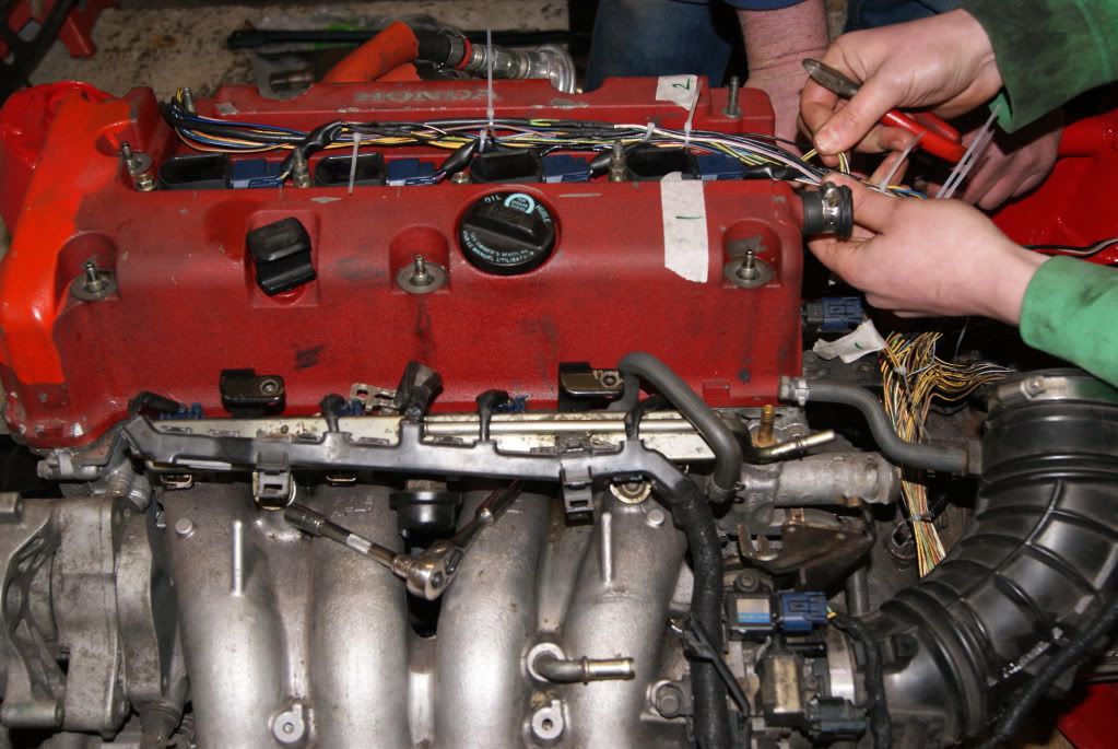
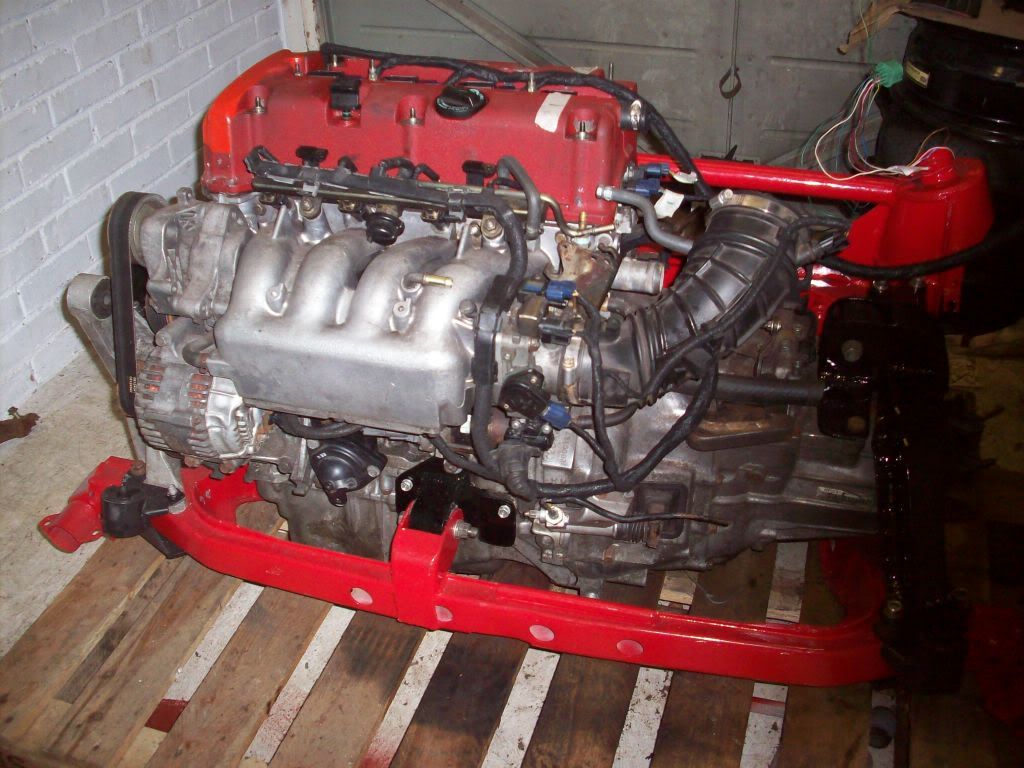
    btw this is MY standard of work... this is me and my mats putting a K20A2 Civic Type R V-TEC engine, in a MG-TF, using a Rover25 loom to make up wires the right colour... we solodered and heat shrank the lot and then wrapped it in proper loom tape so it maintained shape and such


  15. #15
    Guest
    Join Date
    Jun 2009
    Location
    walsall/tamworth
    Posts
    6,746
    Rides
    0
    if someone has a decent picture of a standard engine bay that should help you a bit.
    the extra wire on the lambda sensor plug looks to be a bodge to repair the broken wire going into the back of the plug. the wires get brittle with heat.

    the idle valve wants connecting to the cold side intercooler pipe.

    join the breathers together and vent one into a catch can. on the back of the inlet plenum you will see another breather you want to block this off. on the rubber turbo to air flow meter pipe you will see a small inlet and a bigger inlet block both of these off, some people use a screw and a spark plug.

    under the throttle butterfly you will see some small takeoffs run a hose from your actualtor to one of these.

    the idle valve should click when you turn the ignition on. take it off and clean it up as they get full of oil and grime.

    the black connectors on the passenger strut are for the cold start solinoid that you dont have anymore so dont worry about them

  16. #16
    Guest Ross S14's Avatar
    Join Date
    Apr 2005
    Location
    Clyst Honiton, Devon
    Posts
    3,820
    Rides
    0
    That's a hell of a lot of work fella - most would probably jack it in! I hope it owes you pennys?

  17. #17
    Guest R3K1355's Avatar
    Join Date
    Nov 2006
    Location
    Yorkshire
    Posts
    12,176
    Rides
    0
    Nonsense thats some simple bay tiding up there, alittle homework and some cheap connectors and pipes is all it needs.

  18. #18
    Guest M.D.'s Avatar
    Join Date
    Jul 2005
    Location
    plymouth
    Posts
    10,631
    Rides
    0
    Shouldn't take long at all. Just look at a few stock engine bay pics and see where things went.
    And get a copy of the workshop manual as some of the pics in there should show you how the plugs should look and there locations

    The wire on the lambda is for a NARROW band AFR gauge that people add to the dash. Had one for years in mine till I started mapping and got a wide band.

    Looks like its had an idle problem in the past which is why the AAC valve is bodged. Maybe they suspected a leak.

    The small vac pipes on the turbo. Just get one from the front housing and loop it to the actuator mounted to the side of the turbo. That will give you stock boost or there abouts and should be ok to test the car.

    The breathers on top of the rocker covers just need the two horizontally facing pipes plumbed together and the one vertical one plumbed to a catch can.

    The breather at the back of the inlet can be blocked.

  19. #19
    Guest Adam-Murse's Avatar
    Join Date
    Jun 2012
    Location
    Teesside
    Posts
    284
    Rides
    0
    OK guys the Saga continues....

    the car now has 444cc injectors so should have been read to bosst... instead it ran naff and now it's not boosting and then started to run on 3 cylinders (oh joy)

    one thing however that i've worked out is hat i have the pipe from the actuator connected to the wrong place... dr_innosent s13 kindly took this picture for me...


    "the pipe that disapears goes to the wastegate actuator"

    well the pipe from my wastegate actuator doesn't go to a boost controller (I don't have one atm) and it doesnt go to a hot I/C pipe... instead i've plummed it to where another vac pipe comes from the turbo area... it's the "other" pipe im holding in this pic


    this seems to be the most likly cause of my issues to me

    but no idea why it's now spluttering like hell

  20. #20
    Guest Bahnstormer's Avatar
    Join Date
    Jun 2005
    Location
    Bournemouth
    Posts
    4,393
    Rides
    0
    Wow, that's quite a project you've got there! Looks like whoever did the wiring in my Golf also did the wiring in your S13 lol.

Posting Permissions

  • You may not post new threads
  • You may not post replies
  • You may not post attachments
  • You may not edit your posts
  •