


So I put this together today to help others actually wire in their own Apexi's. Because pictures paint a thousand words and because I couldn't find anything myself when searching for this. (And mainly because I was bored and was thanking my lucky fecking starts I had some wiring to do!)
Anyway:
Step 1. Disconnect the battery - Mine doesn't exist because my charge pipes have made use of the battery tray.
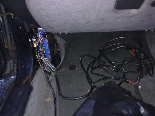
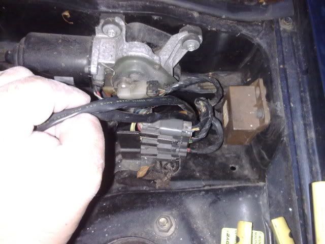
Step 2. Remove the passenger kick panel via two phillips screws to find the ECU.
Step 3. Undo the 10mm bolt all the way out even when it's free spinning.
Step 4. Take the business end of the Apex'i wiring and do the following:
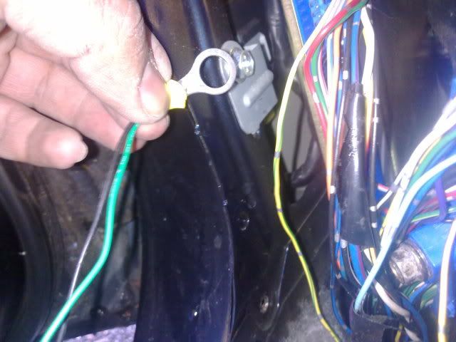
Connect the green and black to ground:
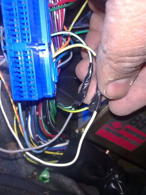
Connect the grey wire to pin 38 Throttle signal. That is to the light green wire with a black stripe. Connect the White wire to pin 53 - Yellow with a green strip: The Speed Sensor:
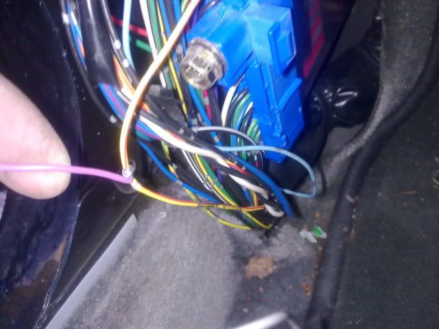
Now connect the Purple wire to pin 7 - RPM Signal: Yellow with a red stripe:
And the remaining red wire goes to pin 59 which is +12v ECU power. This is the second last one on the bottom row to the RIGHT of the ECU plug. It's Black with a white stripe.
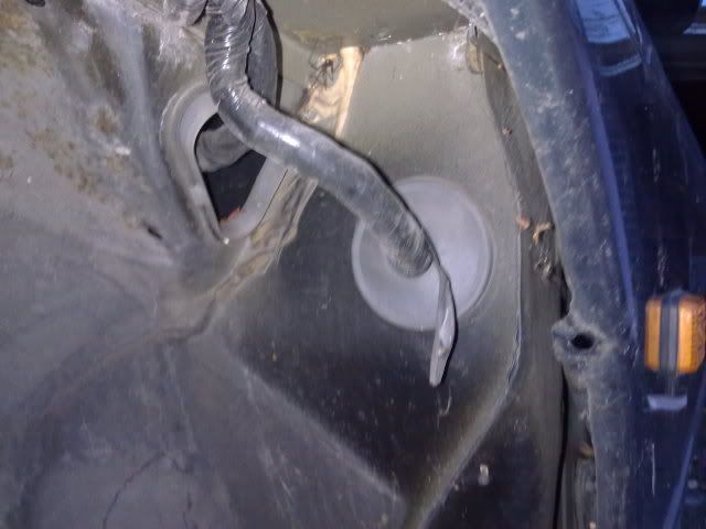
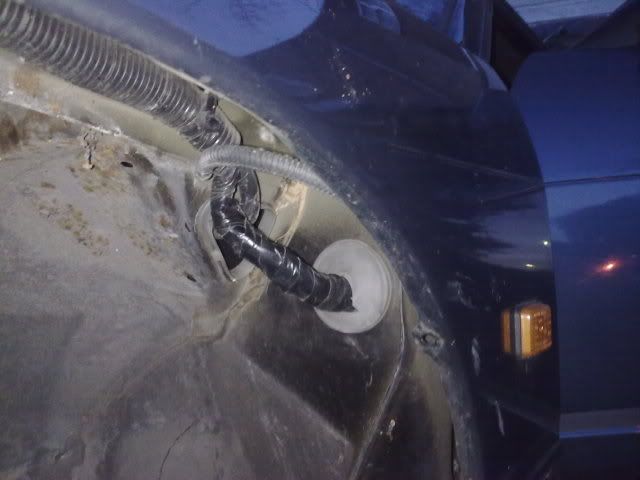
So far this is all I've done, the next mission is to remove the passenger side wheel arch liner so I can access the rubber grommets to push the boost and solenoid valve plugs through. I will Update this with the relevant pictures.
Tosseef Hussain.


 Reply With Quote